Glass Patents UK class 56 - 1867

PATENTS FOR INVENTIONS. ABRIDGMENTS OF SPECIFICATIONS

CLASS 56, GLASS. — From Bound volume 1855-1900, printed 1905

Patents have been granted in all cases, unless otherwise stated. Drawings accompany the Specification where the abridgment is illustrated and also where the words Drawings to Specification follow the date.

{Glass-Study: Redrawn images are ©2008 F. E. Andrews. Layout ©2008 Glass-Study.com (F Andrews). All text is in the public domain. Pagination is ignored as only reference needed for citation is year and Patent Number.}

A.D. 1867.

Patent Abridgment 1867 133

133. Weldon, W. Jan. 18.

Materials — for making glass. An artificial peroxide of manganese, containing over 55 per cent. dioxide, and useful for glass manufacture, is made by injecting air into a mixture of a lower oxide of manganese and water. The air may be heated.

Patent Abridgment 1867 143

143. Bull, W., [Baudoux, L.]. Jan. 19.

Blowing. — A blowpipe carrier, Fig. 1, is formed with jaws P mounted by hinges B upon a fork A, one end G of which screws into a hinged rod, which may be provided with adjustable lengthening-pieces, and is supported by a shaft on a travelling frame running on rails outside the furnace. The jaws P are connected by a spring C with clasps D, to which is hinged the pipe holder F, which can be adjusted by a thumb-piece E operating on the spring C. The blowpipe, Fig. 17, is formed with a flange, which rests on rollers in the holder F, Fig. 1, and is free to turn on a horizontal axis; it may be fitted with a movable ring M, working between welded rings N, which hold the movable ring when the pipe is vertical. Or the pipe may be formed with grooves into which the ring M fits by means of studs. To handle the pipe when attached to the molten glass a catch is employed consisting of a jointed or other rod carrying either a pair of opposite rollers v, v, Fig. 21, or a double crotchet B, A, Fig. 33, of which the jaw B is fixed and the jaw A movable. The travelling frame, Fig. 25, to which the blowpipe carrier is attached, consists of two wheels joined together by a shaft; it is controlled by means of a hand or treadle lever fixed under the blower's stage and attached to a lever M actuating a catch L which checks the motion of the frame before it reaches the wooden stop K; this stop is supported by a spring H, which, acting through hinges G, presses the brake F down on the wheels A. When a travelling frame is not used, the rod r, Fig. 19, to which the blowpipe carrier is attached, is secured to a rod q connected with pulleys p which run on rails s, or to a single pulley; or three pulleys, Fig. 36, may be employed, of which two p, p run on a rail s, the third pl being guided by an upper rail o. The blower's stage L, Fig. 3, is formed with hinged branches H, in which are notches for the finished cylinders, and which are fitted with rollers P and guides K. The stage may be supported at any required height and moved in any required direction by means of a simple crane provided with a projecting arm on which the stage rests; this arm may also be formed with rollers to support the blowpipe.

Perforating. — A sharp wedge M, Fig. 30, is mounted on the shaft of a small spur-wheel N, which gears with a larger wheel O operated by a handle P.

©2008 Glass-Study.com

©2008 Glass-Study.com

Patent Abridgment 1867 1120

1120. Breakell, J. W. April 16.
[Provisional protection only.]

Transparencies; transparent materials. — For making imitation stained glass for windows, cotton or other fabric or paper, printed in colours, is rendered transparent, if necessary, by saturation with oil, and is then stuck on to the sheet of glass by means of varnish or cement; a second sheet of glass is similarly secured to the back of the design.

Patent Abridgment 1867 1914

1914. Rees, G. June 29. [Provisional protection only.]

Moulding tablets &c. — Powdered glass, dry or in paste and either with or without the admixture of metallic oxides or other colouring-matter, is pressed into a mould, the cover of which is afterwards forced on. The article is then fired, either by itself or in the mould, and may subsequently be polished.

Patent Abridgment 1867 1921

1921. Duce, W. July 2.

Moulding bottle stoppers. The stopper consists of a glass &c. cup or cover having a female screw which fits on a male thread on the neck of the bottle. The Figure shows apparatus for moulding the stopper. The mould b is closed by a hinged cover d, operated by a handle e and held down by a clamp h. When the mould has been filled with molten metal, the screw k is screwed down to the required depth to form the female screw; the extent to which the screw is lowered is determined by a nut l &c.

©2008 Glass-Study.com

Patent Abridgment 1867 2114

2114. Hargreaves, J. July 19.

Materials. — Steel slag, or the steel cinder obtained in making steel &c. by the process described in Specification No. 2046, A.D. 1867, [Abridgment Class Iron &c.], is used in the manufacture of glass by fusing it with silica, lime, and lead or zinc oxides or other glass-making materials.

Patent Abridgment 1867 2257

2257. Hue, L. V., and Rozière, C. Aug. 5.

Moulding; pressing; ornamenting. — The required designs are impressed upon the glass when almost in a state of fusion, by means of punches or stamps with or without colours, and other pieces of hot glass are welded on, thus producing articles with smooth exterior surfaces and interior 
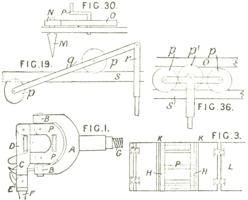
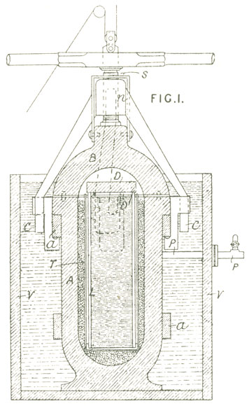
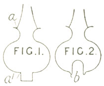
ornamentation. Fig. 1 shows a press for forming knobs for doors &c. The molten glass is placed in a matrix A, and the engraved stamp b is impressed thereon by means of the lever B. A covering-piece of glass, moulded to the required shape and size, is placed while very hot over the matrix, and is welded to the ornamented glass by pressure of jaws G, operated horizontally by levers H. A similar knob &c. may be produced by stamping the design in the interior of a blown cylinder while in the mould, and afterwards bending the edges towards each other, so that the ornamentation is enclosed in a hollow knob. 
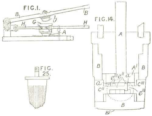
Paper-weights, baluster knobs, &c. may be similarly ornamented. In some cases, for ornamenting decanters, smelling-bottles, drinking-glasses, vases, &c., a cast-iron box B, Fig. 14, is used, containing engraved stamps C11, C111, &c. having tail-pieces e11, e111, &c., which catch into slots a in a foot-piece A1 on a screw rod A. The box B, which may be engraved on the bottom B1 and may be also grooved or fluted, is lowered by means of a press into a matrix containing the glass, which is almost fused. The rod A is then turned, and the foot A1 drives out the stamps C11, C111, &c., thus ornamenting the glass. By turning the rod A in an opposite direction the stamps are withdrawn, after which the box B is removed. A piece of white or coloured glass of the required size and 
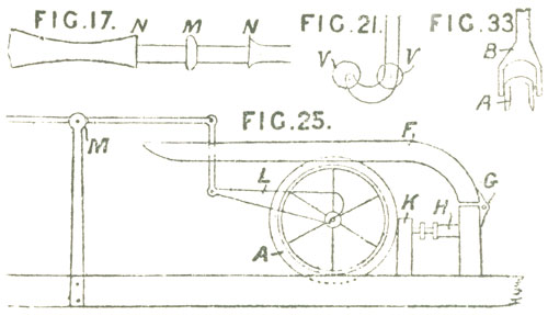
shape is then placed within the matrix and welded to the ornamental glass. Fig. 25 shows a stamp suitable for ornamenting tubes for decorating rooms, &c. In forming lustre plates or "fiddle drops," the mould is made in two parts connected together by a strong hinge. Each half carries a matrix in which the glass is placed, to be ornamented by stamps. After the stamps are withdrawn, the halves of the mould are brought together, by pressing a handle, and the halves of the plate are thus welded together. According to the Provisional Specification, the process may also be applied to the manufacture of lamp globes, salt cellars, inkstands, terminal ornaments for bedsteads, curtain rods, water bottles, inkstands, &c.

©2008 Glass-Study.com

Patent Abridgment 1867 2912

2912. Rives, J. Oct. 17.

©2008 Glass-Study.com

Moulding. — Pressure is applied to glass castings while solidifying, to render them dense and homogeneous. The mould L is placed in a strong vessel A, which can be closed airtight by a cover B forced down by a screw s working in a nut n carried by hooked arms c engaging under a ring a on the vessel A. After the molten metal has been poured in the mould, the vessel A is closed, and compressed air is admitted through a pipe P. When it is desirable to apply heat to the substance during solidification, the mould is surrounded by a thin metal case T, between which and the internal surface of the vessel A pieces of charcoal are packed. When the molten metal is poured in, it ignites the charcoal. A thin plate D1 is placed on the top of the molten metal, and a thick plate D of fireclay is placed over the top of the mould. The vessel A is kept cool by immersion in water in a vessel v.

Patent Abridgment 1867 2983

2983. St. Martin, H. R. Oct. 24.
[Provisional protection only.].

Dividing glass. — Pieces of coloured glass for ornamenting glass surfaces are produced by allowing an acid to eat through a sheet of glass along the outline of the figures required.

Patent Abridgment 1867 3158

3158. Landells, S. Nov. 8. [Provisional protection only.]

©2008 Glass-Study.com

Blowing, moulding, and finishing lamp globes &c. — Relates to methods of manufacturing glass globes and other hollow forms for gasaliers, chandeliers, candles, lamps, &c. The glass is blown into a suitable mould to give it its general form, and is finished afterwards. In one method, the article takes the shape shown in Fig. 1, grooves a and a1 being formed, the latter by the addition of a small cup or projection. This is cut off while the glass is hot by passing a wetted tool round the groove a1.The same process is afterwards applied to the groove at the top. The bottom may be made to assume the form shown in Fig. 2, the cup being inverted and leaving a rim b. This is afterwards ground off, allowing the cup to fall out. The bottom may also be blown continuous with the sides, and placed when hot upon a cold metal ring to cut out the hole. The blowpipe can be used at the bottom of the article, which may be formed with patterns or plain.